Apogee W/C Card Mod For Switchable Termination
As previously stated, the Apogee W/C card input is hard wire terminated. If you are adept with a soldering iron and a few tools, you can make it switchable between terminated and unterminated.
To do this, you will need a single pole, double throw, miniature toggle switch, some tinned copper hook-up wire and a 75 ohm, metal film, 1/4 watt, 1% resistor. Metal film resistors generally have a 5 band color code. A 75 ohm resistor is represented by:
- Purple = 7
- Green = 5
- Black = 0
- Gold = Multiply by 0.1
- Brown = 1% tolerance
So for a 5 band code, we have, 750 X 0.1 = 75 ohm.
If the resistor has a 4 band color code then 75 ohms is represented by:
- Purple = 7
- Green = 5
- Black = Multiply by 1
- Brown = 1% tolerance
So for a 4 band code, we have, 75 X 1 = 75 ohm.
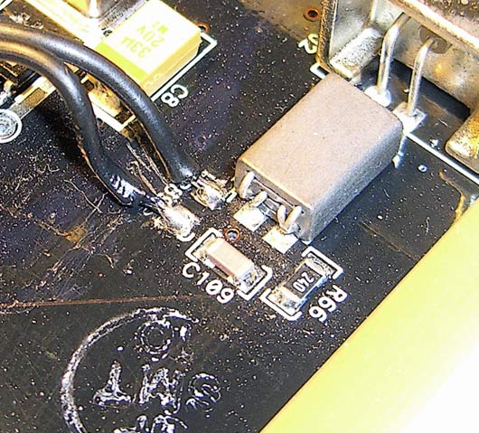
Read Un-Terminating The Apogee Wordlock Card first and remove the 75 ohm resistor (R89) from the board. The following pic (courtesy: Mike Rivers) shows where it is:
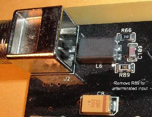
Re-tin the solder pads on the board where the removed resistor previously was.
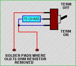
This diagram shows what needs to be achieved:
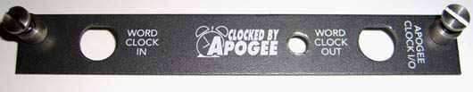
Unscrew the nuts and remove the washers of the BNC connectors that hold the fascia plate to the card.
Place the fascia plate in a vise, firmly gripping it by the long edges and drill a 1/4 inch hole, dead center between the “Clocked by Apogee” and “Word Clock Out” legends. Use a larger drill (1/2 inch) to gently remove any burrs on each side of the hole like so:
Solder the resistor and two flying leads of about 3 inches long as shown in the following pic:
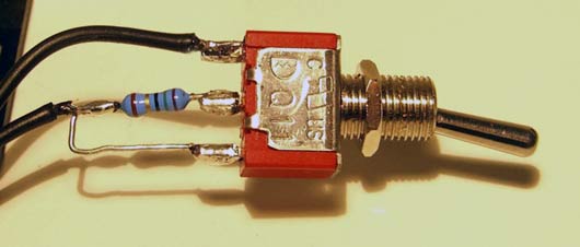
Re-attach the fascia plate to the board with the nuts and washers and insert and tighten the switch in the orientation shown below:
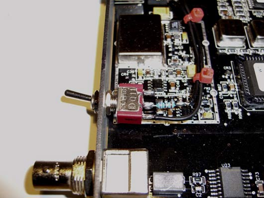
and:
Trim, strip and tin the flying leads so that they may be neatly soldered to the pads on the board where the removed resistor previously was. Polarity is irrelevant with resistors.
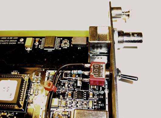
Solder the leads to the tinned pads and tie the two leads together with some miniature cable ties to keep them neat and close to the board to make insertion and removal from the d8b painless:
Your card should now look like this:
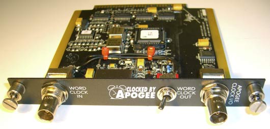
The card can now operate unterminated (switch position – up) or terminated ( switch position – down).
This is pretty basic stuff but, as always, if you don’t have the necessary skills or don’t feel confident enough to perform this mod and you still want it done, get a tech to pop around.
Channel Reversal (Odd/Even)
It has been reported, on occasion, that the odd/even channels can wind up reversed. ie., an input to channel 1 reads on and is controlled by channel 2 and vice versa.
A possible explanation and some solutions, follow:
Many digital formats have signals travel in pairs over the same wire (multiplexing). The transmitting chip will put out a sample of one signal (odd channel), then a sample of the other (even channel). Clock signals keep them synchronized and allow the receiving chip to put each of the samples in their correct place. The d8b is just such a device and sends signals in pairs over a single wire, internally.
If the clock signal and audio data get far enough out of sync with each other, the receiving chip will displace the samples, putting them into the wrong signal path and the odd/even signals will trade places.
This situation occurs sometimes when making a digital transfer betweeen two pieces of gear that are not clocked from the same source.
Here are some things to try if you experience this phenomenon:
Rebooting fixes many problems.
If you are clocking from an external word clock, try booting with your clock source off and then try booting with it on. Some d8bs like to boot with the word clock source on, others like it off (that is, they will only boot properly one way).
There may be a problem with your clock card. Try reseating it. With the power off, pull it out and put it back in again. It may be a good idea to clean the contacts with an eraser.
If you have access to another clock card, try using it instead. For instance if you use the Apogee word clock card, but still have the stock (internal only) card, see if it works with the stock card. If the stock card works, it could be an indication that the Apogee card has a fault.
Finally, you may have to have a service center look at it. Check with Mackie tech support first, just in case they have other tricks for you to try.
Distribution and Termination
If you are using the d8b as the master wordclock for your studio and you are chaining that wordclock to a few devices, then the last device in the chain is the one that should be terminated.
Eg:
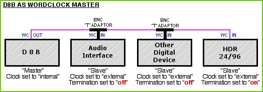
Note that BNC “T” connectors are used to chain the clock. You do not connect to “Clock In” of a device and then chain “Clock Out” from that device to the next.
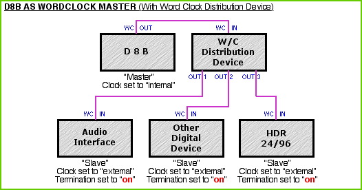
If you have a wordclock distribution device and you want to distribute the d8b’s wordclock via that device, then all equipment connected should be terminated.
Eg:
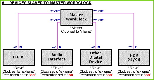
If you have a Master Wordclock like an Apogee “Big Ben” or similar then, all devices connected should be terminated.
Eg:
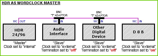
The Apogee Wordclock Card "in" connector is hard wire terminated and you cannot make it unterminated without performing a little internal surgery (see Un-Terminating The Apogee Wordclock Card and Apogee W/C Card Mod For Switchable Termination) so if you choose to clock the d8b in a chain like fashion from say, an HDR 24/96 and there are other devices in the chain (the reverse of the top diagram), then the d8b will need to be placed last in the chain with all other devices unterminated.
Anomaly: (There’s always one)
It has been discussed that the Apogee wordclock card for the d8b has a marginal output voltage and may not drive the HDR 24/96 with enough juice in order for the HDR to be terminated. If you have an HDR and you experience this problem, just leave it unterminated. It’s not ideal but it is a solution that may apply to other devices as well. The HDR will lock up reliably if the termination is off, but this can increase jitter and it might be audible under some conditions.
Alternatively, it is believed that the HDR 24/96 has a stronger clock output and should be used as the Master clock when working with just a d8b or when other devices are included in a chained set-up.
Eg:
Finally, always remember to set the correct sample rate (44.1KHz or 48KHz) for each of your devices. They may auto sense but it's better to be safe than sorry.
Ribbon Cable Connection Correction Procedure
The ribbon cables used to connect the various PCBs in the console have contacts that may become loose over time, possibly due to repeated cycles of heating and cooling (expansion and contraction). Just the slightest misconnection can cause interruptions to signal or power, producing frustrating problems and hours of troubleshooting and down-time.
One of the major problems caused by these loose connections is loss of wordclock sync. The main culprit seems to be an unstable connection between any of the internal ribbon cables and the back-plane PCB. The back-plane PCB is attached to the back of the card cage which all the I/O cards, effects cards and the clock card plug into. Because this PCB is central to the d8b's data/signal flow, the symptoms of a loose connection are not limited to just loss of wordclock sync, but other strange behavior as well.
The Symptoms of Lost Wordclock Sync
When the d8b loses wordclock sync, 99% of the time it will lose all functions relating to digital I/O, resulting in no audio or audio only on one side of the L/R bus. You may also see one or more of the 26 LED meters light up all the way and remain there. You may also notice a flashing */? indicator in the upper right hand corner of the fluorescent display on the d8b. All these are signs of lost sync. You may experience one of them or all of them.
Note: Most likely--because no conversions (A-D or D-A) are required to do so--the console may still pass audio through any of its three analog 2-track inputs, and then out to its 2-track analog outputs. Don't be fooled into thinking wordclock must be working correctly for this to happen.
The Major Suspect
One ribbon cable in particular may be the cause of the problem, that is the ribbon cable which runs from the back-plane PCB to the Power Distribution PCB, which is mounted inside the console and connected to the “BFG” (Big Fricking Connector). If this ribbon cable moves at all, then power to the clock card may be interrupted and cause loss of sync.
The First Step
The first thing to try when sync is lost is to remove the clock card (stock or Apogee) and clean the contacts with a good brand of contact cleaner (Caig DeoxIT is highly recommended for this purpose) and then reseat the card. This may or may not cure the problem. This procedure can also be applied to the MFX/UFX or I/O cards, if you're suspecting trouble with them or you just want to try everything in order to get back to making music.
A few things happen during this process:
- 1. The contacts are cleaned
- 2. The card is reseated and a better connection may take place
- 3. By reseating the clock card, the back-plane PCB is flexed a little bit. This is possibly the most important part of the process because it tends to reseat the ribbon cables into the back-plane PCB, and that may be all it needs.
This procedure may, at least temporarily, fix the problem regarding loss of sync. If it does, excellent. If, however, you soon find that you are losing sync again, a slightly more difficult procedure (and not for the faint of heart) may be necessary.
Going Inside
This procedure is not hard if you are technically, mechanically and electronically inclined, but you will have to dive in where few have gone before. In doing this, precautions absolutely MUST be taken to avoid damage to parts in the d8b that are prone to damage from ESD (electrostatic discharge).
You must first ground the d8b, and then ground yourself to either the d8b or the ground that you have grounded the d8b to. If you do not feel comfortable working with electronics and are not aware of the standard precautions that must be taken, don't proceed by yourself. Either get someone who does understand electronics to help you, or have it done by a competent service engineer. The tech support people at Mackie will be happy to recommend an authorized repair shop in your area.
If you do decide to take this on, getting to the ribbon cables is actually quite easy.
- 1. Disconnect the d8b from its power source.
- 2. Carefully lay the console on its face, either on a cushion or blocked up so that the faders don't take all of the weight. It's a good idea to move the faders to their maximum position so that the elbow rest and not the faders are bearing the weight.
- 3. Remove the screws holding the bottom cover and set them aside in a safe place.
- 4. Remove the bottom cover.
- 5. Once you've removed the bottom cover, make sure to ground the d8b and yourself to a good ground source. A cold water pipe (not hot water) is normally a very good grounding point.
- 6. With the back of the d8b facing away from you, you will see a small PC board that attaches to the BFC (Big Fricking Connector) on the back left-hand side. Mounted on the PC board are a couple of large capacitors. Please be aware that even though the d8b is disconnected from the mains, capacitors can still hold a charge for quite some time and they can zap you. It's best to just avoid this circuit board, other than to give the ribbon cables on that board a good pull/push to make sure they are seated securely.
- 7. To the right of that PC board, you will see the card cage and the many ribbon cables that are attached to it. Very carefully, and to avoid any confusion, remove ONE end of ONE cable at a time and clean the ribbon connector and the PC board connector with a good grade of contact cleaner. It's best to use the liquid type with the small foam applicators. You can get them at any electronics store. They work better than the spray type because you can control the application in a more precise manner. After cleaning, reseat the connector.
- 8. Repeat this procedure on all the ribbon cable connectors and double check to make sure all the cables are restored to their proper places.
- 9. Replace the bottom cover making sure not to over tighten the screws. Because of the flexibility of the d8b's case/frame, it's best to put all the screws in loosely first and then tighten them up once they're all in place.
This procedure has worked to repair quite a few d8bs that had problems with losing wordclock sync, and other ailments, too.
Here is a link to photos showing the ribbon cables and the back-plane PCB:
Addendum
To keep from having trouble with loose connections, something that's possibly worth doing is to lock the ribbon cable connectors down by applying a small dab of adhesive to each end of the connector. Dow Corning offers a line of Silicone adhesives that may well do the job. DO NOT run down to your local hardware store and buy "standard" silicone RTV (the ones that smell like vinegar). The fumes these products produce when curing WILL corrode copper and other materials used in electronic components and circuit boards. It is also best to use a non-flowing RTV as it will not sag during the curing process.
There is a list of electronics compatible silicone adhesives from the Dow Corning website that will give you a selection of various silicone products that should work. There is also a link there to find distributors for their products in your area.
To lock them in place, you only need a very small dab of adhesive on the outside of the connectors (where the male and female connectors join together). A small amount is advisable since you may want to remove these cables at a later date.
Troubleshooting Word Clock erros
Word clock errors can manifest themselves in a variety of ways, all unpleasant. The audible effects can include subtle, intermittent digital distortion, random soft “ticks”, loud digital noises, speed and pitch errors, muted audio and frozen meters.
To test for word clock issues, set the console to internal clock (Windows menu>Setup>Digital I/O), and disconnect all digital audio and BNC word clock devices. If your problem persists, it probably is not word clock related (unless you have a bad d8b clock card or connections. See:
Every d8b SHOULD be fitted with the optional Apogee word clock I/O card for best performance.
If you have a word clock problem (other than hardware malfunction), it can be caused by: conflicts resulting from multiple clock sources, a weak clock signal due to chaining devices, or improper termination settings.
SPDIF, AES and Lightpipe digital audio all have word clock signals embedded with the audio. Generally, a dedicated BNC clock connection is superior and more reliable.
Reconnect your digital devices to the d8b one at a time to isolate a conflicting device.
Be sure that all devices are set to the same sample rate (44.1 or 48 kHz), and are properly terminated (maybe a setting in hardware or software, fixed or automatic). The device should normally be terminated unless it is not the last receiving device in the clock chain.
Be sure that only one device is set as "master" (set to run on and output it's own internal clock). All the others should be set to sync to incoming word clock if connected by BNC, and to digital audio if receiving via AES, SPDIF or Lightpipe.
Many engineers suggest using either the clock source known to be superior, or the clock of the 2 analog to digital converter as the master clock for the system.
If you have more than two BNC word clock devices in your system, you might need a dedicated word clock generator/distribution device with multiple clock outputs such as those made by Apogee, Lucid, and (formerly) Aardvark. Or you MIGHT be able to use a BNC "Tee" connector or daisy chain to pass the clock signal from one device to the next. Generally, using a Tee or daisy chain is the less desirable solution.
Different manufacturers have adopted their own standards for signal strength in their word clock implementations, so solutions may vary according to each unique system configuration. The solution with the least audible side effects and best stability is optimal. That may seem obvious, but the point is that there is no single "optimal" word clock set up that makes sense for every system.
Forum members have expressed different opinions regarding the importance of high quality BNC cables. Given the critical role of word clock in a studio with a digital console, and the insidious nature of the artifacts of errors, many feel that this is not a place to cut corners.
Un-Terminating The Apogee Wordclock Card
The Apogee wordclock card input is hard wire terminated. If you have the know-how, you can remove the termination, if so required.
The following picture (courtesy: Mike Rivers) shows exactly which resistor does the terminating and if you find it absolutely necessary to have the d8b in the middle of a wordclock chain and of that necessity, un-terminated, you can remove the resistor. It may also help if you are clocking the d8b from a master wordclock that is known to have a marginal output (eg., Big Ben)
Be aware that although the resistor looks easy to remove, in real life, it is minute. You will need a desk mounted magnifying glass, a solder sucker, a very hot soldering iron, a perfectly working pair of tweezers and plenty of light. Place the board on a folded tea-towel or similar fabric and locate on a solid surface. This is to stop the board jumping about when you activate the release button of the solder sucker's plunger. Melt the solder at each end of the resistor and suck the solder quickly. Only heat each end once, then wait 30 seconds or so to allow the board to cool down before having another go if you didn't get all the solder the first time. Don't dwell with the iron or you may risk lifting the copper pads off the board which would render replacement of the resistor very difficult indeed. Make sure that once the resistor is removed, no stray bits of solder have found their way between the pads or fallen onto another part of the board.
Needless to say, if you don't feel comfortable attempting something like this, don't do it yourself. Get someone qualified to do it.