Battery
If'n yer battery acts up ornery, holler fer a new one.
CR 2032
or
DL 2032
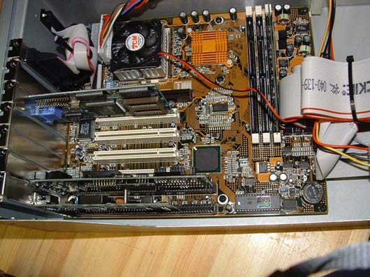
Here you can see its location on the motherboard.
And here you can download the Battery Replacement Procedure in PDF format.
Fan: Replacing with a quieter model
The little 50mm (2”) cooling fan located over the CPU on the motherboard is a noisy beast and it gets noisier over time. In fact, the cowling can warp and it can sound like an outboard motor when you first boot the d8b, gradually getting less noisy as the PSU warms up and the warped cowling attempts to return to its previous shape.
If you appreciate silence in your studio, then this little pest is worth replacing and the prime candidate is a Zalman
FB 123. Zalman’s website can be found here where you can do a search for the unit and for the distributor in your
country.
The FB 123 is larger than the fan originally fitted to the CPU and you will need to do a bit of gerry-rigging to get it
installed but it is remarkably quiet and without a doubt, worth the minimal effort.
When you purchase the FB 123 kit, this is what you receive:
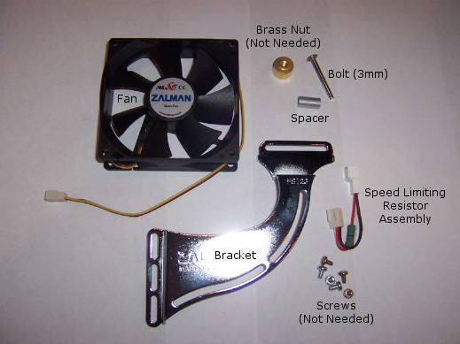
Because fitting a generic device like this to our specific friend is not quite cut and dried, you’ll need 2 x 3mm hex
half nuts (not supplied) to mate with the 3mm bolt included in the Zalman kit.
This procedure assumes that you are working from the left hand side of the CPU with the front to your right (as in
the pix). It is also important to have the CPU plugged into a grounded AC outlet with the power turned off at the
mains and to constantly touch the chassis or power supply to discharge any static electricity that may build up in
your body as you move about.
Assemble the fan and bracket like so:
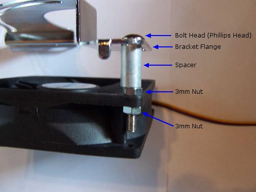
and like so:
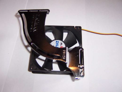
Make sure the bolt and nuts are tight and the assembly is square. Don’t overtighten the nuts in case you strip the threads.
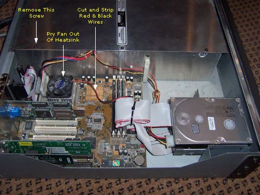
Unscrew the 18 screws from the CPU cover and remove. Remove the back screw holding the top aluminum plate of
the PSU in place. Carefully pry the old fan off the heatsink on the CPU and cut the red and black wires and strip them back about 1/4” on the side that runs to the power supply.
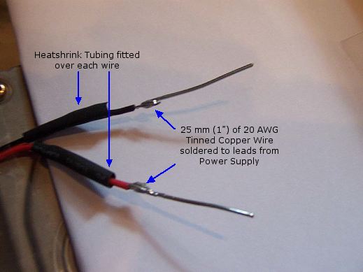
Solder about an inch (25mm) of 20 AWG tinned copper wire to each of the bare red and black fan lead wires that you have just stripped. Get an appropriately sized piece of heatshrink tubing and slip over the two wires, hiding the solder joints. Shrink the tubing with a hair dryer or heat gun, leaving about 1/2” (12mm) of the tinned copper wire protruding.
Soldered wires prior to heatshrinking:
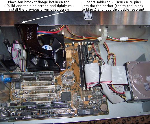
Place the flange of the fan bracket between the PSU lid and the top lip of the side screen and replace the previously
removed screw. Before tightening, slide the assembly so that the left hand side of the fan’s cowling is in line with
the left hand side of the CPU. Secure tightly, again being careful not to strip the thread.
Plug the speed limiting resistor assembly into the connector at the end of the Zalman fan lead (it’ll only go in one
way) and then poke the two 20 AWG “pins” into the red and black sockets at the other end respectively making sure
that the heatshrink tubing sits up neat with the connector.
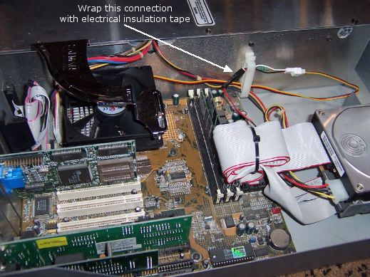
Finally, wrap some electrical insulation tape around the connector where the “pins” enter to keep them secure. Place the wires in the available cable restraint.
As an alternate and more secure method of connecting the new leads to the old, cut the connector off at the power supply end of the speed limiting resistor assembly, strip the red and black leads back about 1/4" and solder directly to the original wires that run to the power supply, remembering to slip some heatshrink tubing on each wire first. Shrink the tubing over the splice and you're good to go. You might like to clip the white wire of the resistor assembly at the fan side connector for the sake of neatness. It and the yellow wire of the fan's leads are not used. They are there for speed control by temperature sensing power supplies of which, the d8b is not one.
One advantage in going the "pin" route is that you have the choice of choosing to use or not use the speed limiting
resistor assembly. The fan is not that much noisier without it and you may decide to let it just spin at full speed. It's
up to you and you should check it both ways and make your own value judgement. If you choose to not use the
speed limiting resistor assembly then it would definitely be worth hard wiring the fan leads to the power supply
leads sans the connector.
Boot the CPU to ensure that the fan is doing what it should. It should be spinning anti-clockwise. If it’s going
clockwise, you got the wires reversed.
When all is OK, replace the cover and enjoy the serenity.
Flashing "Memory" Indicator
At the top of the VDU, to the right of the Menu section and to the left of the "Session" name indicator, is another little indicator that shows the "Memory" available for further data entry.
Sometimes, after long periods of heavy use and Automation procedures, the displayed number
can begin flashing between 0 and a higher number. It doesn't matter what that higher number
is.
If this happens, it is a sure sign that something is amiss and you should save your work
immediately, preferably with a suffix ammendment and re-boot.
Meter Overload Indicator Inaccuracies
The meters on the d8b indicate O/L (red) early. This was supposedly to help users by offering a margin for error.
The Channel O/Ls come on at -0.95 dBfs.
The L/R Master O/Ls come on at -0.58 dBfs.
0dBfs = Full scale digital = you don’t have no more headroom for those cowbell transients.
Note that all digital audio meters, hardware and software, use their own meter ballistics which are not standardized. Some show red lights as low as -4 or -5 dBfs. Others, at a certain number of samples reaching or approaching full scale. Some devices have user adjustable settings for this parameter.
Also note that there is really no such thing as an "Overload" (in the analog sense) at a digital
input, as the input cannot receive a signal greater than full scale (although there is certainly a
risk of overloading circuits before or after the input). Of course, the analog stage of an analog
to digital converter can be overloaded.
The "OL" indicators or red lights on digital inputs should be thought of as warnings, rather than
as a precise indicator of signal strength, loudness or distortion.
Video Monitor Refresh Rate for V5 and V5.1: Warning
Do not attempt to change the Video monitor Refresh Rate under “Windows
menu>Setup>Refresh Rate” if using O.S. V5 or V5.1.
This may incur a fatal crash that can only be rectified by a full format of your HD and
re-installation of the OS.
Mackie report:
Issue #40: Changing the refresh rate has no effect.
Workaround: None. Do not change the refresh rate.
Some users have reported problems, others have not. Whatever, to change it makes no
difference to the monitor’s appearance so it’s best left alone.
If you have not kept back-ups of all mixes etc. and this problem occurs, you will lose all of
your data.
It would be advantageous to grab a copy of the known issues regarding V5.1 OS by
downloading this PDF file so that you are fully up to speed with any anomolies.
Voltage (AC) Differences
If you intend to purchase a used d8b on eBay or elsewhere, you need to be aware that there were two different power supplies installed in the CPU rack to accommodate the different ac mains voltages in different countries. It is not an auto power sensing or switchable supply.
They are:
110 - 120 Vac (60 Hz)
220 - 240 Vac (50 Hz)
Make sure that you get a d8b CPU rack with a power supply that is suited to the mains voltage in your country.
If you come across an irresistable bargain which has say, a 110 V power supply and your country’s supply is 240 V, you will need a high quality stepdown transformer. Likewise, you will need a step up transformer if going the other way.
It’s feasable that the internal transformers and fuses could be swapped out with ones appropriate to your needs but it is highly discouraged unless you have a complete working knowledge and understanding of electronics theory and construction.
Don’t blow it!! Get a stepdown or stepup transformer.
Alternatively, acquire a CPU rack that matches your voltage and keep the one that comes with the console for spares.
CPU Power Supply Replacement
Power Supplies within the CPU/PSU rack
1. Aztec Supply:
This is the first of two 5V power supplies in the CPU/PSU rack, this one being a switching power supply which provides the D8B with 5VDC, one of many supply voltages required by the board to drive its circuitry. If this supply blows, the console will appear dead although the CPU will boot up. After fully booted up, the monitor will display an error message ("reset").
2. Sparkle Supply:
This is the 5V power supply for the CPU.
3. Linear Power Supply:
A small circuit board dominated by several large capacitors which provides a variety of DC voltages to the D8B console, including +48V (for phantom power), + 12 VDC, and +/- 16 VDC.
If the Sparkle 5V power supply in the CPU rack dies, a replacement is available in the form of a Sparkle Power Supply model SPI-250G.
Error 32
If you experience a message stating, 'Opening Document. Error 32 File Bad Checksum' whilst trying to load a session and you've gone thru all the regular procedures of checking that the BIOS settings are correct and the battery is sound, it may be worth a try to clear the CMOS and re-enter the BIOS settings from scratch. Clearing the CMOS can be done a few ways:
1. If you have the older motherboard, remove the battery from the CPU and leave it out overnight or for 12 hours or so.
2. If you have the newer motherboard, refer to the following picture:
![]()
Unplug the power cord. Move the jumper over from its original position so that it's connecting the center pin to the pin toward the battery. Leave it there for about 10 minutes, then put it back in its original position. When you power up, it will probably tell you to press F1 to load the defaults. Do that and then go through the whole list of settings.
3. If you have a PC, a good resource for BIOS surgery is eSupport, the people who support the Award BIOS used in the d8b and HDR. The utility CLRCMOS.EXE, which can be downloaded from that web page, will do the same thing as removing the battery overnight or setting the Clear CMOS jumper. There's also a boot disk (self extracting to a floppy) to boot the CPU into DOS so you can run CLRCMOS.